Replacing a Wheel Speed Sensor Without Damaging Its Wiring
I’ll clarify the parts of a wheel speed sensor replacement that cause the most trouble: freeing a seized sensor, preserving the harness and clips, and confirming that the ABS fault is actually gone. You’ll also learn when a damaged connector or hub makes this job more than a sensor swap.
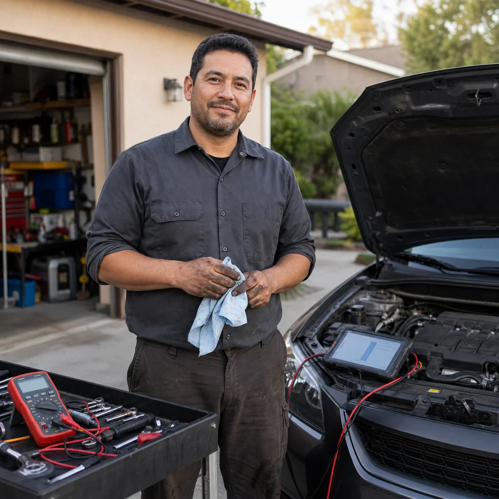
Replacing a wheel speed sensor is often described as a simple remove-and-replace job. The electrical connector may unplug easily, but the sensor can be rusted into the knuckle, its wire may be trapped by suspension movement, and a routing mistake can let the tire or axle damage the new harness. A successful repair depends as much on protecting and positioning the wiring as it does on installing the sensor.
This procedure applies broadly to common magnetic and Hall-effect wheel speed sensors, but mounting details vary considerably. Use the vehicle’s service information for sensor location, fastener torque, connector locations, and any required calibration procedure. Some vehicles use a separate sensor; others integrate the speed sensor into a hub or bearing assembly, in which case replacing the sensor alone may not be possible.
Confirm the vehicle-specific procedure: Before loosening anything, check the service information for your exact year, model, drivetrain, and brake system. Verify whether the sensor is replaceable separately, where its connector is located, how the harness is clipped, and whether ABS initialization or steering-angle calibration is required afterward.
What you need before starting
Gather a floor jack, appropriately rated jack stands, wheel chocks, basic hand tools, a torque wrench, penetrating fluid, a flashlight, and a way to support or protect the electrical connector. A small pick or trim tool can help release clips, but avoid using sharp tools against the wires. A scan tool that can communicate with the ABS module is strongly preferred; a basic engine-code reader may not be able to read or clear ABS faults.
Wear eye protection when working around rust and brake dust. The vehicle must be supported by jack stands on solid ground, with the wheels that remain on the ground chocked. Never rely on the jack alone. If you need to turn the steering wheel for access, keep the vehicle securely supported and account for the possibility that the suspension or steering position will change the harness tension.
Before disassembly, photograph the original sensor wire from the connector to the sensor. Include every clip, guide, bracket, and bend in the image. This is especially useful on the front suspension, where the harness often follows a specific route around a strut, knuckle, brake hose, or control arm.
Diagnose the fault before removing the sensor
A warning light doesn't prove that the sensor itself has failed. An ABS code can result from a damaged harness, corroded connector terminals, an incorrect air gap, a damaged tone ring or encoder, a wheel bearing problem, low system voltage, or a fault in the ABS module. Read the ABS module and record all codes and live-data symptoms before clearing anything.
Inspect the suspected corner with the wheel turned for access. Look for rubbed insulation, stretched wire, broken retaining clips, corrosion inside the connector, and evidence that the harness has contacted the tire, axle, spring, or rotor. Compare the sensor and harness with the opposite side when the vehicle uses a symmetrical layout, but don't assume both sides are routed identically on every model.
If live data is available, compare the four wheel-speed readings while turning the wheel by hand or during a cautious road test, as appropriate for the fault. A reading that drops out, stays at zero, or differs from the others can help identify the corner, but it doesn't by itself distinguish a sensor from a wiring or tone-ring problem.
Remove the old sensor without pulling on the wire
After securing the vehicle and removing the wheel, trace the harness all the way to its connector. Release the connector from its body-side bracket before disconnecting it if that is the manufacturer’s method. Press the locking tab rather than pulling on the wire. If dirt is packed around the connector, clean the outside first so debris doesn't enter when the halves separate.
Remove each harness clip deliberately. A clip that looks like a simple push-in fastener may have a locking tab, a sliding retainer, or a small bolt. Prying against the insulation can cut or crush the wire. If a clip is already broken, note its position; the replacement sensor needs an equivalent secure attachment, not merely a loose wire hanging near the original route.
Apply penetrating fluid around the sensor’s mounting area and allow it time to work. Avoid spraying indiscriminately onto brake friction surfaces. Remove the retaining bolt with the correct tool and steady pressure. If the bolt is heavily corroded, clean the head first and use a suitable penetrating process rather than rounding it.
A seized sensor should be treated as a corrosion problem, not as a reason to yank harder on the harness. Twist the sensor gently if it has enough exposed body to grip, and work it back and forth. You can tap the sensor body lightly with an appropriate punch or small hammer, but protect the surrounding knuckle and don't strike the connector or wire. On some vehicles, the old sensor may need to be sacrificed and drilled or broken out. That is a point where patience matters: drilling too deeply can damage the tone ring, bearing, or knuckle.
If the sensor won't come out without risking the hub, bearing, tone ring, or steering knuckle, stop and reassess. The cost of professional extraction is usually lower than repairing a damaged mounting surface or replacing additional wheel-end parts. Don't heat an area containing seals, grease, plastic components, or a sensor harness unless the vehicle-specific procedure explicitly supports it and you understand the risks.
Prepare the mounting surface and new sensor
Once the old sensor is out, remove loose rust and debris from the bore and mounting face. Use a suitable brush or pick carefully, keeping material out of the bearing and away from the encoder or tone ring. Don't enlarge the bore or scrape the sensor’s sensing tip. A sensor that sits too high, too low, or at an incorrect angle may produce a fault even if the electrical circuit is good.
Compare the replacement with the original before installing it. Check the connector shape, wire length, mounting tab, sensor body, and clip locations. An aftermarket part can be electrically compatible but still have a harness that doesn't follow the original path safely. If the wire length or molded guides differ substantially, verify the application rather than stretching the wire to make it reach.
Install the sensor straight into its bore. Don't force it with the mounting bolt; the bolt should secure the sensor, not pull a misaligned part into place. Use only the lubricant or anti-seize specified for that vehicle and location. Products on the sensing tip can attract debris or alter the sensor’s position, and excess compound can migrate into areas where it doesn't belong.
Tighten the retaining fastener to the vehicle’s specified torque. Avoid substituting a remembered value from another model, because small sensor fasteners and mounting materials vary. If the bolt or clip is damaged, replace it with the specified type rather than using a generic tie or an overlong fastener near a rotating component.
Route the replacement wiring like a moving part is nearby
Start at the sensor and work toward the connector, installing each clip in the original position. The harness should be supported without being stretched. Leave only the amount of movement designed into the original route, especially where the steering knuckle moves relative to the body. A wire that looks neat with the wheel straight may become tight at full steering lock or full suspension travel.
Keep the harness away from the tire, rotor, axle, spring, and sharp edges. Maintain the original separation from the brake hose and other moving parts. Don't twist the cable into a shorter path, pull it taut, or secure it to a brake hose with an improvised fastener. The harness must flex where the suspension and steering require movement, but it mustn't swing into a rotating assembly.
Before reinstalling the wheel, turn the steering from lock to lock while watching the harness. If the vehicle is safely supported and the design permits it, check the suspension through its usable movement as well. Look for stretching, pinching, contact, or a clip that releases. Compare the result with the photographs and with the opposite side, while remembering that the original side may itself have been incorrectly routed after earlier work.
Reconnect the electrical connector until its lock engages. Inspect the terminals for pushed-back pins, moisture, or green corrosion. Don't force a connector together if it won't seat; find the obstruction or confirm that the connector is correct. Secure the connector in its bracket so its weight and vibration don't load the sensor wire.
Clear the fault and verify the repair
Reinstall the wheel and tighten the lug nuts using the vehicle’s specified procedure. With the vehicle on the ground, use a capable scan tool to read the ABS module again. Some faults clear only after the module sees a valid signal, while others may require a deliberate code-clearing command or an ignition cycle. Clearing the code without checking live data doesn't confirm the repair.
If the scan tool displays wheel-speed data, compare the repaired corner with the others at low speed in a safe location. The readings should rise smoothly and remain plausible rather than dropping out intermittently. A road test should follow the manufacturer’s conditions where known, and you should choose a quiet area away from traffic. Avoid deliberately provoking an ABS event just to test the repair.
After the test, rescan the ABS module and inspect the harness once more. Confirm that the warning light behaves normally and that no new fault has appeared. If the original code returns, don't repeatedly clear it. Recheck the connector, terminal tension, harness routing, sensor seating, bearing play, and tone ring or encoder condition. A new sensor can't compensate for a damaged reluctor or a wheel bearing that changes the sensor gap.
When the sensor isn't the real repair
A wheel speed fault that changes when the harness is moved points toward wiring or terminal damage. A signal that varies with bearing movement may indicate a hub or bearing issue. On some systems, the encoder is part of the bearing seal, making the bearing assembly the relevant component rather than the sensor. A missing or damaged tone-ring tooth can also create a repeating signal problem that looks like a sensor failure.
If the connector is broken, the wires are damaged inside the insulation, the sensor is seized in a critical wheel-end part, or the ABS module can't communicate, the job has moved beyond a straightforward replacement. Likewise, professional help is sensible if you can't safely support the vehicle or verify that the harness clears every moving and rotating part.
The safest replacement is one that preserves the original electrical path and confirms the result through ABS-module data. Take time to document the route, free the old sensor without loading its wire, clean the mounting surface, and test the repaired corner before treating the warning light as solved. That approach reduces the chance that a new sensor becomes damaged by the same condition that ruined the old one.